Quantcast
Channel: can-bus – Hackaday
Viewing all 56 articles
Browse latest View live

Don’t Sleep On The Lawn, There’s an AI-Powered, Flamethrower-Wielding Robot About

$
0
0
Flamethrower weedkiller mounted on a robot arm riding a tank tracked base

You know how it goes, you’re just hanging out in the yard, there aren’t enough hours in the day, and weeding the lawn is just such a drag. Then an idea just pops into your head. How about we attach a gas powered flamethrower to a robot arm, drive it around on a tank-tracked robotic base, and have it operate autonomously with an AI brain? Yes, that sounds like a good idea. Let’s do that. And so, [Dave Niewinski] did exactly that with his Ultimate Weed Killing Robot.

And you thought the robot overlords might take a more subtle approach and take over the world one coffee machine at a time? No, straight for the fully-autonomous flamethrower it is then.

This build uses a Kinova Robots Gen 3 six-axis arm, mounted to an Agile-X Robotics Bunker base. Control is via a Connect Tech Rudi-NX box which contains an Nvidia Jetson Xavier NX Edge AI computing engine. Wow that was a mouthful!

Connectivity from the controller to the base is via CAN bus, but, sadly no mention of how the robot arm controller is hooked up. At least this particular model sports an effector mount camera system, which can feed straight into the Jetson, simplifying the build somewhat.

To start the software side of things, [Dave] took a video using his mobile phone while walking his lawn. Next he used RoboFlow to highlight image stills containing weeds, which were in turn used to help train a vision AI system. The actual AI training was written in Python using Google Collaboratory, which is itself based on the awesome Jupyter Notebook (see also Jupyter Lab on the main site. If you haven’t tried that yet, and if you do any data science at all, you’ll kick yourself for not doing so!) Collaboratory would not be all that useful for this by itself, except that it gives you direct, free GPU access, via the cloud, so you can use it for AI workloads without needing fancy (and currently hard to get) GPU hardware on your desk.

Details of the hardware may be a little sparse, but at least the software required can be found on the WeedBot GitHub. It’s not like most of us will have this exact hardware lying around anyway. For a more complete description of this terrifying contraption, checkout the video after the break.


Simplify 3D Printer Wiring With CAN Bus

$
0
0

[mark] had an interesting idea when looking at all the wiring of a typical 3D printer; Use CAN Bus. There are a lot of wires going to the extruder assembly, and with most designs this thing is flying around at quite some speed. You’ve got connections for powering the heater, fan power, four wires for the extruder motor, thermistor sensor wires. You get the idea. Lots of wires. Worse, they’re all moving around with the axis, and if failures occur at either end due to poor strain relief, or the conductors themselves break, then all manner of interesting failures can occur. If the hot end thermistor connection goes open circuit, usually no damage occurs but the temperature control goes out the window and your print will fail.

Now if you push the electronics needed to drive and control the extruder, directly onto the moving body itself, and hook-up to the main printer electronics with CAN Bus, you can do the whole moving interconnect thing with a measly four wires. Yes, you need another PCB assembly, so it adds cost, but it does also simply the electronics at the control end, so some savings can be made. [mark] has used CAN Bus due its availability with modern microcontrollers and also its designed-in robustness, thanks to its automotive and industrial heritage. When you think about it, this is a rather obvious thing to do, and we’re not sure why we’ve not see it much before.

If you want to dig into the detail, the project GitHub has the schematics and code ready to go.


Volvo C30 Custom Gauge And CAN Bus Reverse Engineering

$
0
0

With cars being essentially CAN buses on wheels, it’s no wonder that there’s a lot of juicy information about the car’s status zipping about on these buses. The main question is usually how to get access to this information, both in terms of wiring into the relevant CAN bus, and decoding the used (proprietary) protocol. Fortunately for [Alex], decoding the Volvo VIDA protocol used with his Volvo C30 was relatively straightforward, enabling the creation of a custom gauge that displays information like boost pressure and coolant temperature.

The physical interfacing is accomplished via the car’s OBD port, which conveniently provides access to the car’s two (high-speed and low-speed) CAN buses. Hardware of choice is an M2 UTH (Under the Hood) board, sporting a SAM3X Cortex-M3-based MCU, designed for permanent automotive installations. On [Alex]’s GitHub project page it is explained how the protocol works, and which bytes to look for when replicating the project.

Rounding off the project is a round LCD display from 4D Systems that cycles through the status update screens. As a bonus, the dashboard illumination level is also read out in real-time, so the brightness of the display is adjusted to fit this level. All in all a well-rounded project, with interesting prospects for a more permanent integration of the gauge into the dashboard proper.

Probing CAN Bus for EV Battery Info

$
0
0

The widespread adoption of the CAN bus (and OBD-II) in automobiles was largely a way of standardizing the maintenance of increasingly complicated engines and their needs to meet modern emissions standards. While that might sound a little dry on the surface, the existence and standardization of this communications bus in essentially all passenger vehicles for three decades has led to some interesting side effects, like it’s usage in this project to display some extra information about an electric car’s battery.

There’s not a ton of information about it, but it’s a great proof-of-concept of some of the things CAN opens up in vehicles. The build is based on a Citroën C-Zero (which is essentially just a re-badged Mitsubishi i-MiEV) and uses the information on the CAN bus to display specific information about the state of charge of the battery that isn’t otherwise shown on the car’s displays. It also includes a build of a new secondary display specifically for this purpose, and the build is sleek enough that it looks like a standard part of the car.

While there are certainly other (perhaps simpler) ways of interfacing with a CAN bus, this one uses off-the-shelf electronics like Arduino-compatible microcontrollers, is permanently installed, and has a custom case that we really like. If you’re just starting to sniff around your own vehicle’s CAN bus, there are some excellent tools available to check out.

Thanks to [James] for the tip!

CAN Peripheral For RP2040, Courtesy Of PIO

$
0
0
Part of a picture showing all kinds of different CAN devices in a car

[Kevin O’Connor] writes to us about his project, can2040adding CAN support to the RP2040. The RP2040 doesn’t have a CAN peripheral, but [Kevin] wrote code for the RP2040’s PIO engine that can receive and send CAN packets. Now we can all benefit from his work by using this openly available CAN driver. This library is written in C, so it’s a good fit for the lower-level hackers among us, and in all likelihood, it wouldn’t be hard to make a MicroPython wrapper around it.

The CAN bus needs a peripheral for the messages to be handled properly, and people have been using external chips for this purpose until now. These chips, [Kevin] tells us, have lately been unavailable due to the chip shortage, making this project more valuable. The documentation is extensive and accessible, and [Kevin] details how to best use this driver. With such a tool in hand, you can now turn your Pico into a CAN tinkering toolkit, or wire up some CAN devices for use in your own projects!

[Kevin] says this code is already being used in Klipper, a framework powering 3D printers and other machines like them. As for your own purposes, you can absolutely use such a CAN tool to hack on your car – here’s a treasure trove of car hacking documentation, by the way! Thanks to the PIO engine, there seems to be no end to the RP2040’s versatility – you can even drive HDMI monitor with this PIO-based DVI code.

Title picture by Florent.david.lille1, CC BY-SA 3.0

This Week in Security: QueueJumper, JS VM2 Escape, and CAN Hacking

$
0
0

You may not be familiar with the Microsoft Message Queuing (MSMQ) service, a store and forward sort of inter-process and inter-system communication service. MSMQ has become something of a legacy product, but is still available as an optional component in Windows. And in addition to other enterprise software solutions, Microsoft Exchange turns the service on by default. That’s why it’s a bit spooky that there’s a one packet Remote Code Execution (RCE) vulnerability that was just patched in the service.

CVE-2023-21554, also known as QueueJumper, is this unauthenticated RCE with a CVSS score of 9.8. It requires sending a packet to the service on TCP port 1801. The Check Point Research team scanned for listening MSMQ endpoints on the public Internet, and found approximately 360,000 of them. And no doubt far more are listening on internal networks. A one packet exploit is a prime example of a wormable problem, and now that the story has broken, and the patch is available, expect a rapid reverse engineering. Beware, the queue jumpers are coming.

JavaScript VM Escape

The VM2 library is a rather important JavaScript package that sandboxes code, letting a project run untrusted code securely. Or, that’s the idea. CVE-2023-29017 is an example of how hard sandboxing is to get right. It’s another CVSS 9.8 vulnerability, and this one allows a sandbox escape and code execution.

This one now has public Proof of Concept code, and this package has over 16 million monthly installs, so the attack surface is potentially pretty wide. The flaw is fixed in version 3.9.15.

Oldsmar Errata

Remember the scary hack of the water treatment plant at Oldsmar? Someone attempted to raise the Sodium Hydroxide levels from a sane 100 ppm up to an unpleasant 11,000 ppm. We even had a bit of fun with the idea that it could have been a watering hole attack on a real watering hole. A few of our more skeptical readers pointed out that the new value felt a bit like a forgotten decimal point, or a fat fingered attempt at a legitimate change.

Well surprise, it’s beginning to look like the null hypothesis was right. “[T]hrough the course of the investigation the FBI was not able to confirm that this incident was initiated by a targeted cyber intrusion of Oldsmar.” The city manager made a statement that it may have even been the reporting employee, accidentally banging on the keyboard. So, that’s awkward. Though it suggests a new hobby, similar to trainspotting: Looking for debunked attacks in presentations. This particular non-incident seems to be one of the favorite for government officials to mention when asking for money or pushing for new regulations.

CAN Bus Zero Day

Modern cars are technological marvels. Components that used to be dead simple, like headlights, are now micro computers in their own right, all networked together over a data bus. The traditional data bus is the Controller Area Network (CAN) Bus, though Automotive Ethernet threatens to toss CAN on the heap of legacy technology. That time has not yet come, and most vehicles still have a CAN bus. Which brings us to the story of [Ian Tabor], a security researcher driving a RAV4.

That vehicle got vandalized one day, with some trim around the headlight being torn off in a seemingly random act of mayhem. A couple days later, when the car was stolen, it became clear that it wasn’t vandalism at all. The headlight just happens to be an easy place to access the CAN bus. When the car was stolen, it experienced a major system fault, and uploaded a log of what all was broken. Turns out, pretty much all of the connected devices dropped off that CAN bus. That’s an interesting part of what’s going on here.

This vehicle, and many others, use a smart key. It’s a bit of hardware that does a reasonably secure cryptographic handshake via wireless, with the wireless receiver. That receiver, upon validating the key, sends a message across the CAN bus that unlocks the vehicle. Wireless cryptography: good. CAN cryptography? Nonexistant. The hack is self-contained in a $10 hardware kit, that gets punched in to the car’s CAN bus where the headlight connects to it. It first does a DOS attack of sorts, knocking the real key receiver off the bus, and then sends a flurry of spoofed messages, telling the rest of the car that the smart key is present. And as a result, the push-to-start button works without complaint.

This is a zero-day attack that’s ongoing against a bunch of vehicle vendors. The researchers behind this discovery have attempted to report their findings, and have run up against a brick wall trying to do normal responsible disclosure. The research report ends with a request for an auto manufacturer or industry group to reach out and assist with the next steps of research and trying to fix this mess for the various vulnerable vehicles.

Bits and Bytes

How do you confirm that a printer isn’t unintentionally spying on you? Rooting the printer and doing an audit, of course. It’s a potential problem that printers save copies of documents to an onboard hard drive, and RedTeam Pentesting wanted to know whether their local printer was guilty of this indiscretion. The hack was to backdoor the printer via the… literal back panel, and finding a serial port. Many embedded devices have a TTL-level serial port, and that port is often not well secured. In this case, the login was console, and one of the menu options was sh mode. Which of course dropped into a root shell on the device. Oh well. At least they confirmed their documents were properly being erased after printing!

There’s a weird trick with Github account names. When you change your account name, Github is nice enough to put up redirects, so the old URLs still work. But the old name is actually an unused account name, that anyone can use to sign up. And now those redirects go away, or if the new user recreates the repositories, they go to the new code. All is fine, until you realize that sometimes build systems are pointing at old usernames. That’s exactly what [Joren Vrancken] found in the Arch User Repository, as well as for a single package on the official Arch repositories. The attack to take advantage of this quirk is called repo jacking, and it’s worth thinking about if you’re a developer or maintainer of software.

Eve Online saw a heist this week, where the equivalent of $22,300 was drained from an in-game corporation. The approach was depressingly similar to a real-world corporate takeover. In this case, [Flam_Hill] managed to get a handful of voting shares, and then applied for membership in the corporation with a couple of accounts. Once accepted, those voting shares granted the right to call for a snap election for CEO. That voting process is open for 72 hours, and because this corp didn’t have a particularly active pool of voters, only the shell accounts cast votes, putting our attacker in complete control. Turns out, that attacker was none other than [Sienna d’Orien], original founder of the corporation, returned from a hiatus to take back his company. Game imitates life indeed.

And finally, Juice Jacking! It sounds like the newest bodybuilding technique of questionable legality, but in fact, it’s a rather old idea for cell phone hacking. Offer free cell phone charging, but secretly use the USB data connection to install malware. It’s such an ongoing problem that the FCC and FBI have recently issued warnings against using untrusted USB charging. Except, no one seems to have actually seen this attack in the wild. And digging a bit into those warnings, the primary source is a District Attorney’s warning, that was later retracted due to no actual cases on record. So let us know, have you ever actually seen a juice jacking attack?

Sufficiently Advanced Tech: Has Bugs

$
0
0

Arthur C. Clarke said that “Any sufficiently advanced technology is indistinguishable from magic”. He was a sci-fi writer, though, and not a security guy. Maybe it should read “Any sufficiently advanced tech has security flaws”. Because this is the story of breaking into a car through its headlight.

In a marvelous writeup, half-story, half CAN-bus masterclass, [Ken Tindell] details how car thieves pried off the front headlight of a friend’s Toyota, and managed to steal it just by saying the right things into the network. Since the headlight is on the same network as the door locks, pulling out the bulb and sending the “open the door” message repeatedly, along with a lot of other commands to essentially jam some other security features, can pull it off.

Half of you are asking what this has to do with Arthur C. Clarke, and the other half are probably asking what a lightbulb is doing on a car’s data network. In principle, it’s a great idea to have all of the electronics in a car be smart electronics, reporting their status back to the central computer. It’s how we know when our lights are out, or what our tire pressure is, from the driver’s seat. But adding features adds attack surfaces. What seems like magic to the driver looks like a gold mine to the attacker, or to car thieves.

With automotive CAN, security was kind of a second thought, and I don’t mean this uncharitably. The first goal was making sure that the system worked across all auto manufacturers and parts suppliers, and that’s tricky enough. Security would have to come second. And more modern cars have their CAN networks encrypted now, adding layers of magic on top of magic.

But I’m nearly certain that, when deciding to replace the simple current-sensing test of whether a bulb was burnt out, the engineers probably didn’t have the full cost of moving the bulb onto the CAN bus in mind. They certainly had dreams of simplifying the wiring harness, and of bringing the lowly headlight into the modern age, but I’d bet they had no idea that folks were going to use the headlight port to open the doors. Sufficiently advanced tech.

Car Security System Monitors Tiny Voltage Fluctuations

$
0
0

As the old saying goes, there’s no such thing as a lock that can’t be picked. However, it seems like there are plenty of examples of car manufacturers that refuse to add these metaphorical locks to their cars at all — especially when it comes to securing the electronic systems of vehicles. Plenty of modern cars are essentially begging to be attacked as a result of such poor practices as unencrypted CAN busses and easily spoofed wireless keyfobs. But even if your car comes from a manufacturer that takes basic security precautions, you still might want to check out this project from the University of Michigan that is attempting to add another layer of security to cars.

The security system works like many others, by waiting for the user to input a code. The main innovation here is that the code is actually a series of voltage fluctuations that are caused by doing things like turning on the headlights or activating the windshield wipers. This is actually the secondary input method, though; there is also a control pad that can mimic these voltage fluctuations as well without having to perform obvious inputs to the vehicle’s electrical system. But, if the control pad isn’t available then turning on switches and lights to input the code is still available for the driver. The control unit for this device is hidden away, and disables things like the starter motor until it sees these voltage fluctuations.

One of the major selling points for a system like this is the fact that it doesn’t require anything more complicated than access to the vehicle’s 12 volt electrical system to function. While there are some flaws with the design, it’s an innovative approach to car security that, when paired with a common-sense approach to securing modern car technology, could add some valuable peace-of-mind to vehicle ownership in areas prone to car theft. It could even alleviate the problem of cars being stolen via their headlights.


Get MOST Into Your Pi

$
0
0

When looking the modify a passenger vehicle, the Controller Area Network (CAN) bus is a pretty easy target. In modern vehicles it has access to most of the on-board systems — everything from the climate control to the instrument cluster and often even the throttle, braking, and steering systems. With as versatile as the CAN bus is, though, it’s not the right tool for every job. There’s also the Media Oriented Systems Transport (MOST) bus which is increasingly found in automotive systems to handle multimedia such as streaming music to the stereo. To access that system you’ll need to approach it slightly differently as [Rhys] demonstrates.

[Rhys] has been working on replacing the dated head unit in his Jaguar, and began by investigating the CAN bus. He got almost everything working with replacement hardware except the stereo, which is where the MOST bus comes into play. It provides a much higher bandwidth than the CAN bus can accommodate but with almost no documentation it was difficult to interact with at first. With the help of a Raspberry Pi and a lot of testing he is able to get the stereo working again with a much more modern-looking touchscreen for control. It is also able to do things like change CDs in the car’s CD player, gather song information from the CD to display on the panel, and can perform other functions of the infotainment center.

For more detailed information on the MOST bus, [Rhys] also maintains a website where he puts his discoveries and other information he finds about this system. Unfortunately car stereo systems in modern vehicles can get pretty complicated these days, but adapting car stereos in older vehicles to modern technology carries some interesting challenges as well.

ESP32 Used As Wireless CAN Bus Reader

$
0
0

The CAN bus, accessible through the OBD-II port, is the channel that holds all the secrets of the modern automobile. If you want to display those for your own perusal, you might consider this nifty tool from [EQMOD].

Yes, it’s an OBD-II dongle that you can build using an ESP32 WROVER module. It’s designed to read a car’s CAN bus communications and display them on a self-hosted web page, accessible over WiFi. The build relies on the dual-core nature of the ESP32, with the first core handling CAN bus duties via the SN65HVD230 CAN bus transceiver chip. The second core is responsible for hosting the web page. Data received via the CAN bus is pushed to the web user interface roughly every 60 to 100 milliseconds or so for information like RPM and speed. Less time-critical data, like temperatures and voltages, are updated every second.

It’s a neat little thing, and unlike a lot of dongles you might buy online, you don’t need to install some dodgy phone app to use it. You can just look at the ESP32’s web page for the data you seek. The graphics may be a little garish, but they do the job of telling you what’s going on inside your car. Plus, you can always update them yourself.

Getting to grips with the CAN bus is key if you want to diagnose or modify modern vehicles. Meanwhile, if you’ve been cooking up your own electronic vehicular hacks, don’t hesitate to drop us a line!

Unbricking Trains, Uncovering Shady Behavior

$
0
0

The first clue was that a number of locomotives started malfunctioning with exactly 1,000,000 km on the odometer. And when the company with the contract for servicing them couldn’t figure out why, they typed “Polish hackers” into a search engine, and found our heroes [Redford], [q3k], and [MrTick]. What follows is a story of industrial skullduggery, CAN bus sniffing, obscure reverse engineering, and heavy rolling stock, and a fantastically entertaining talk.

Cutting straight to the punchline, the manufacturer of the engines in question apparently also makes a lot of money on the service contracts, and included logic bombs in the firmware that would ensure that revenue stream while thwarting independent repair shops. They also included “cheat codes” that simply unlocked the conditions, which the Polish hackers uncovered as well. Perhaps the most blatant evidence of malfeasance, though, was that there were actually checks in some versions of the firmware that geofenced out the competitors’ repair shops.

We shouldn’t spoil too much more of the talk, and there’s active investigation and legal action pending, but the smoking guns are incredibly smoky. The theme of this year’s Chaos Communication Congress is “Unlocked”, and you couldn’t ask for a better demonstration of why it’s absolutely in the public interest that hackers gotta hack. Of course, [Daniel Lange] and [Felix Domke]’s reverse engineering of the VW Dieselgate ECU shenanigans, another all-time favorite, also comes to mind.

A Dashboard Outside The Car

$
0
0

One of the biggest upsides of open communications standards such as CAN or SPI is that a whole world of vehicle hacking becomes available, from simple projects like adding sensors or computers to a car or even building a complete engine control unit from the ground up. The reverse is true as well; sensors and gauges using one of these protocols can be removed from a car and put to work in other projects. That’s the idea that [John] had when he set about using a vehicle’s dashboard as a information cluster for his home.

The core of the build is an Astra GTE dashboard cluster, removed from its host vehicle, and wired to an Arduino-compatible board, in this case an ESP32. The code that [John] wrote bit-bangs an SPI bus and after some probing is able to address all of the instrument gauges on the dashboard. For his own use at home, he’s also configured it to work with Home Assistant, where each of the gauges is configured to represent something his home automation system is monitoring using a bit mask to send data to specific dials.

While this specific gauge cluster has a lot of vehicle-specific instrumentation and needs a legend or good memory to tie into a home automation system without any other modification, plenty of vehicle gauges are more intuitive and as long as they have SPI they’d be perfect targets for builds that use this underlying software. This project takes a similar tack and repurposes a few analog voltmeters for home automation, adding a paper background to the meters to make them easier to read.

PCB Design Review: Tinysparrow, A Module For CAN Hacking Needs

$
0
0

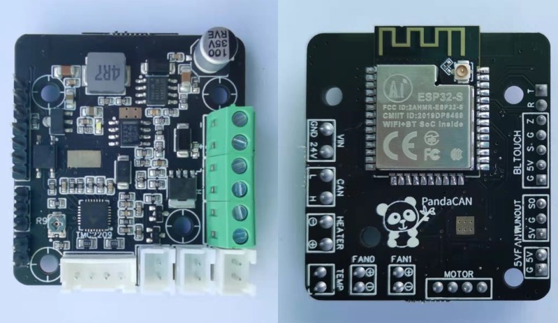
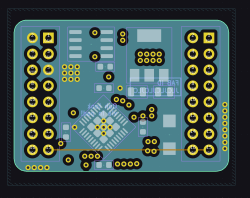
I enjoy seeing modules that can make designing other devices easier, and when I did a call for design reviews, [enp6s0] has submitted one such board to us. It’s a module called TinySparrow (GitHub), that helps you build your own vehicle ECUs and any other CAN-enabled things. With a microcontroller, plenty of GPIOs, a linear regulator and a CAN transceiver already onboard, this board has more than enough kick for anyone in hobbyist-range automotive space – and it’s surprisingly tiny!

You could build a lot of things around this module – a CAN bus analyzer or sniffer, a custom peripheral for car dashes, or even a full-blown ECU. You can even design any hardware for a robot or a piece of industrial technology that uses CAN for its backbone – we’ve all seen a few of those! It’s a great board, but it uses six layers. We’ll see if we can do something about that here.

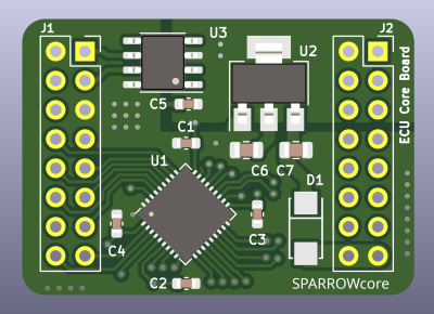
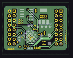
Modules like TinySparrow will make your PCBs cheaper while ordering, too! Thanks to the carefully routed microcontroller and the CAN transmitter, whatever board you design around this chip definitely wouldn’t need six layers like this one does – and, unlike designing your own board, you can use someone’s well-tested and tailored libraries and reference circuits!

With TinySparrow, you save a lot of time, effort and money whenever you want to design a car or industrial accessory. After looking at the board files, my proposal for helping today’s board is – like last time – to make its production cheaper, so that more people can get this board into their hands if the creator ever does try and manufacture it. I also have some tips to make future improvements on this design easier, and make it more friendly for its userbase.

More Layers Not Always Better

Every single pin of the microcontroller is broken out – this matters a lot for such a module. It’s seriouslty annoying when you try to squeeze the most out of the onboard MCU, only to find out that the GPIOs broken out don’t expose one of the critical pins you need. I value such module designs a ton and I think people should be aware of their existence, which is why I’ve just spent time highlighting its strengths.

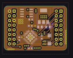
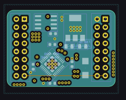
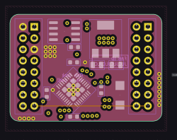
So about those layers. On one hand, this is justifiable for how tiny this design is. Three of these layers contain traces, two are uninterrupted ground fills, and another layer is 3.3 V. This is wonderful for signal integrity, and perhaps this board could really use an extra SI kick. Still, today, I would like to show you how to free up two of the layers, however – in part in case the author struggled to fit things on 4 layers, and in part to show how it’s done.

Six-layer layouts give you superiour signal integrity and a lot of space to route your traces. Often, six-layer boards are nigh unavoidable, like when doing high-speed USB-C altmodes with certain kinds of connectors. However, if these same features could be smooshed down onto four layers, it would be significantly cheaper both for the PCB and assembly.

So let’s get rid of two layers. As you can see, the layers are kinda full, so, some traces would need to be moved. For that, let’s look into the trace layout on this board. The board looks like it exceeds four-layer routing space provisions by a fair bit, but I can show you how it’s not the case!

Tweak The Defaults

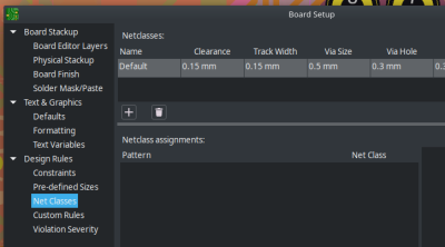
For a start, let’s talk about default parameters, something that ends up limiting this board’s design. This board uses all default KiCad parameters – track widths, clearances, via diameters, and zone values. They are conservative, which is helpful for i.e. etching your own boards, but you lose that benefit if you just order the board, something inevitable at six layers. Let’s go through the distances on this board and see which values we can use while still being totally safe for manufacturing. After we dial the values down, we will have a lot more freedom for rerouting this board!

Track width is at 0.25 mm by default, but it can go as low as 6 mil on any self-respecting fab. Same for the 0.2 mm clearances – they can go to 6 mil too. On 4-layer and 6-layer boards, you can go down to 0.09 mm / 0.09 mm, which especially helps with diffpair layout, but also helps you pull track bundles from point to point.

Vias are 0.8 mm / 0.4 mm (ring width/drill width), which is huge – you can safely drop down to 0.6 mm / 0.4mm on 2-layer boards. At JLCPCB and other fabs, you can drop down to 0.5 mm / 0.3 mm on 4-layer and beyond without paying extra, but even smaller drill sizes tend to cost quite a bit more, so I don’t recommend you use them. As for zone clearances, the default 0.5 mm / 0.25 mm (clearance/minimum width) zone settings are okay, but decreasing them to something like 0.2 mm/ 0.2 mm or lower will help your fills get into tighter spots. On the other hand, solderability of the module’s pin headers will be somewhat worse with solid fills on GND – I would recommend that you use thermals for such boards.

Let’s bulk edit these values! Switching track width to 0.15 mm and via size to 0.5 mm / 0.3 mm, suddenly, a lot of space has cleared up. I was thinking about rotating the microcontroller to allow for higher track density, but now I’m not even sure this is really called for.

Module Pinout

When you design a module like this and expect to have it be used on your and especially others’ boards, changing the pinout is to be done with care – I would know. However, I have strong arguments for why this module deserves a breaking change like that.

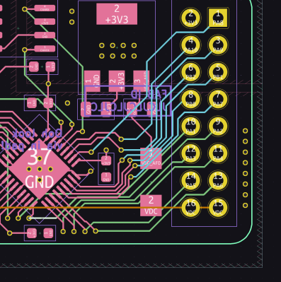
For a start, the module’s GND pins are far and few between – there are only two of them at the CAN header, whereas the module’s actual power inputs and outputs (VDC and 3.3 V) are on the opposide side. This will at least somewhat compromise the return currents for both power and CAN. Remember, there’s a reason we no longer put GND on the opposite side of VCC on modern chips, the way we used to do on DIP-package-era logic ICs.

So, the pin assortment ought to be tweaked. For instance, VDC doesn’t require two pins on the pin header – one of them would be enough, given that the module’s current consumption is quite low. I do acknowledge that breaking pinout changes are quite harmful, but you also have to make sure you make them before the module’s popularity increases. Learning from the Arduino example, the earlier you can make such changes, the better, so if the author is free to replace one of the currently-VDC pins by GND, that will help. You could even add one more GND pin surrounding VFC, replacing one of the near-CAN GNDs with a GPIO – this makes it way, way harder to damage the MCU through accidental screwdriver/metal object/dust application.

Two Layers Removed In Two Minutes

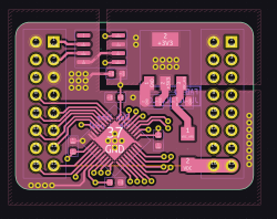
As for layer reduction, let’s look at where traces go. Disabling fill visibility, then selecting only F.Cu, In1.Cu, and In2.Cu, something becomes apparent. While the VIN and module routing on the top interferes with direct signal layout, you could easily move In1 and In2 signals to B.Cu (currently unoccupied).

So, how do you do this reroute? Actually, it took me about two or three minutes. First, move In1 tracks to B.Cu using Edit => Edit Track & Via Properties. Then, tweak the now B.Cu tracks to make sure they don’t overlay with In2.Cu tracks. Last step – move In2.Cu tracks to B.Cu using the same menu. Now we have two outer layers that carry tracks, and four layers that are completely empty, save for their fills – a classic arrangement.

Which layers to get rid of? Three of the now-internal layers have GND and one has 3.3 V. You can delete In3 and In4 by changing the board layer count to 4 in Board Setup menu, and decide what to do with the inner layers. There’s two options – SIG-GND-PWR-SIG, or SIG-GND-GND-SIG. For GND-PWR, the 3.3 V plane only wires up three microcontroller pins, but having it as a power plane improves power current distribution somewhat. Alternatively, you could get rid of the internal power plane, for a relatively classic GND-GND inner layer option, and put the 3.3 V pins on B.Cu – thanks to the F.Cu 3.3 V polygon that the board author added, most 3.3 V-connected elements on the board don’t make all that much use of the inner 3.3 V layer when it comes to power delivery.

By now, the work is already done, and it only took a short while. With four layers, the board is cheaper to manufacture, especially given that the author already took care to only put components on the top layer – props to them. There’s only a few things left that are of note for me.

Silkscreen, And Some Q&A

The silkscreen of this board could use a few additions, in my opinion. For a start, it doesn’t list the board version, which might just bite you, especially given the internal traces! This is true even more so if you’re making multiples of this board and selling it – it really helps your users to know which exact version of the module they have, so that they don’t have to read chip markings or deduce things by trace layout. My preferred format is %BOARDNAME% by %AUTHOR%, v%VERSION%, and this board could very much use a label like this, given that it’s a module.

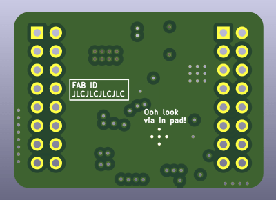
The back of the board is barren, save for the JLCJLCJLCJLC text that safeguards the board’s top layer and a small easter egg. That said, silkscreen is free! There are two options. First option: it could show the module pinout, for the users’ convenience. Second option: it could have some art, for the users’ emotional landscape in one way or another. Choose extra wisely, for both of these choices are wise to make.

Now, here’s a question for the readers – it’s about choosing which components to put onto such a module. This is a board used in an automotive environment – something that is not my domain of expertise, but I’ve read about it here and there, and I wonder if this module would require higher care. For instance, should you put protective elements for the CAN transceiver on this module? CAN termination? Some amount of GPIO protection? Or should these things be relegated to the carrier board, serving as impromptu documentation on the “here’s how you use it” question?

Remember – you, too, can submit your own PCB designs for my review! Send in your board into our tips line, with [design review] in the subject. KiCad is preferred, and a Git repository link desired, but a ZIP file/Google Drive/DropBox link also works. Last but not least, let me know what you think about this feedback, of course – any notes of your own?

A Game Boy Speedometer, Just Because You Can

$
0
0
Game boy with custom cartridge mounted on car dashboard

From a practical standpoint, [John] may be correct that his recent creation is the “world’s worst digital dash”, but we’re still oddly enamored with the idea of using a Nintendo Game Boy as a digital speedometer. Pulling it off meant interfacing the handheld with the vehicle’s CAN bus system, so whether you’re into retro gaming or car hacking, this project has something to offer.

Showing real-time vehicle speed on the Game Boy sounds like it should be relatively easy, but the iconic game system wasn’t exactly built for such a task. Its 2 MHz CPU and 160×144 pixel dot-matrix screen were every kid’s dream in 1989, but using it as a car dashboard is pushing it. To bridge that gap, [John] designed two custom circuit boards. One interfaces with the Game Boy, intercepting its memory requests and feeding it data from a microcontroller. The other processes the CAN bus signals, translating speed information into a form the Game Boy can display. [John] used inexpensive tools and software to read the CAN bus data, and used GBDK-2020 to write the software in C. His video goes in great detail on how to do this.

Months of work have gone into decoding the Game Boy’s data bus and creating a schematic for the interface board. Tricking the Game Boy into thinking it was loading a game, while actually displaying incoming speed data. The screen’s low resolution and slow refresh rate rendered it barely readable in a moving vehicle. But [John]’s goal wasn’t practicality — it was just proving it could be done.

Want to dive deep into the Game Boy?  Have you seen the Ultimate Game Boy talk?

Bosch Starter Motor Freed From Mercedes Prison

$
0
0

Vehicle alternators are interesting beasts. Produced on a massive scale, these electric machines are available for a minimum of cost and contain all kinds of great parts: some power electronics and a belt-driven generator are generally standard fare. This generator can also be used as a motor with only minor changes to the machine as a whole, so thanks to economies of scale it’s possible to get readily-available, powerful, compact, and cheap motors for all kinds of projects using alternators as a starting point. [LeoDJ] noticed that this starter motor in a modern Mercedes had some interesting benefits beyond all of these perks, but it took a bit more work to get up and running than a typical alternator would have.

The motor, built by Bosch, can be found in the Mercedes E200 EQ Boost. This is a hybrid car, but different than something like a Prius in that it doesn’t have an electric motor capable of powering the car on its own. Instead it uses a combination starter motor/alternator/generator to provide extra power to the engine during acceleration, increasing efficiency and performance. It can also charge the small battery bank when the car slows down. Vehicles that use this system need much beefier alternators than a standard car, but liberating it from the car means that it has much more power available than a typical alternator would.

There were a number of issues to solve, though. Being that the motor/alternator has to do all of this extra work (and that it came out of a car whose brand is known for being tedious to work on in the first place) it is much more complicated than an off-the-shelf alternator. [LeoDJ] has been able to get his to spin by communicating with it over the CAN bus, but there’s still some work to be done before it goes into something like an impressively fast electric bicycle.

Thanks to [RoganDawes] for the tip!


Supercon 2024: Yes, You Can Use the Controller Area Network Outside of Cars

$
0
0

Ah, the CAN bus. It’s become a communication standard in the automotive world, found in a huge swathe of cars built from the mid-1990s onwards. You’ll also find it in aircraft, ships, and the vast majority of modern tractors and associated farm machines, too.

As far as [Randy Glenn] is concerned, though, the CAN bus doesn’t have to be limited to these contexts. It can be useful far beyond its traditional applications with just about any hardware platform you care to use! He came down to tell us all about it at the 2024 Hackaday Supercon.

[Randy]’s talk was titled “Yes, You CAN: Use The Controller Area Network Outside Of Cars.” We have to assume the pun was intended. In any case, the CAN bus came to us from Bosch, which began developing the standard in 1983. The company officially released it at the Society of Automotive Engineers conference in 1986, with compatible chips first hitting the market a year later. It took a little while longer for the standard to find traction, with Mercedes-Benz being the first to implement it in a production vehicle in 1991. It soon caught on with the wider industry as a robust and reliable way to let a vehicle’s various control units communicate with all the important sensors that were proliferating on modern automobiles. CAN got its big break when it was mandated as part of the OBD-II standard in North America, which defacto put it into virtually every car sold in that market from 1996 onwards.

Since then, CAN has proliferated well beyond the automotive space, into marine and aerospace contexts as well. As [Randy] explains, beyond transportation, you’ll also find it in everything from robots to pinball machines and even elevators. Basically, wherever it’s important to have robust local communication between distributed embedded systems, CAN is a great candidate for the job.

Since it’s so widespread, it’s easy to find hardware and software that’s CAN-ready out of the box. The vast majority of microcontroller manufacturers include some sort of CAN compatibility; for example, Espressif’s ESP32 has the “Two Wire Automotive Interface” which is built for this purpose. Linux is more than happy to talk CAN, too, and most programming languages have some sort of library available, too. Whether you’re working with Arduino, MicroPython, or CircuitPython, you can certainly find what you need. Even if you have a device without CAN built in—like a Raspberry Pi—SPI-ready CAN controllers can be had for cheap from vendors like Microchip.

Depending on your hardware, you might have to add a CAN controller or transceiver to get it talking on the CAN bus. However, this is usually trivial.

There are specific reasons why you might consider CAN for your embedded communication needs. It uses a differential bus, which gives it an inherent ability to resist disruption from electrical noise. Addressing, error-checking, and retransmission functionality are also baked in to CAN controllers, so you don’t have to handle it yourself. You can also find tons of CAN compatible hardware on the market to do whatever you’re trying to do, and a lot of it is pretty cheap because manufacturers are churning it out by the millions.

Of course, there are some limits. Traditionally, you’re stuck with only 32 devices on a bus, though there are some ways to work around it at lower data rates. Peak data rate is 1 megabit per second on a traditional CAN bus operating at the high data rate; this limits you to a total bus length of 25 meters. You can up this to 250 meters if you drop to 250 kbit/s instead. Packets are also limited to 8 bytes in size.

Beyond the basic performance specs, [Randy] also explains how you might go about typical implementations with different hardware. For example, if you’ve got a microcontroller with no CAN capability baked in, you might hook it up with a CAN controller and transceiver over SPI. Alternatively, you might choose to work with a more advanced microcontroller that has all the CAN communication hardware built into the chip, simplifying your build. For parts like the ESP32 and some STM32s, you might find you’ve got a CAN controller on board, but you’re lacking the hardware to do the fancy differential signalling—in that case, you just need to hook up a CAN transceiver to get your hardware on the bus. [Randy] also highlights the usual conventions, such as terminology and wire colors, while explaining that these aren’t always rigidly adhered to in the field.

Talking CAN on Linux is as easy as plugging in a cheap USB dongle.

On the communication level, the CAN bus standard mandates that nodes transmit frames, with each each frame containing up to 8 bytes of data. [Randy] explains how messages are formatted and addressed to ensure the right nodes get the right data they’re looking for. There are standard message frames, as well as Remote Transmission Request (RTR) frames—where one node requests data from another. A typical example is a controller asking a sensor to report a value. There are also special Error and Control Frames, which [Randy] notes are complicated and beyond the scope of his Supercon talk. However, he recommends resources that exist to explain them in great detail.

Data of a complete CAN frame laid over the traces of the bus itself. Credit: Ken Tindell, Canis Automotive Labs Ltd. via CC BY-SA 4.0

Much of [Randy’s] talk explains how CAN works. But, as promised, he also takes the time to explain possible non-automotive applications for this technology. He steps through an amusing Halloween build, where a CAN bus is used to trigger scary lightning and sound effects when people press a doorbell.

If you’ve ever wanted a good CAN primer, [Randy]’s talk is just what you need. As far as robust embedded communication standards go, it’s one of the most popular and long-lived out there. It might just pay dividends to put the CAN bus in your own toolbox for future use!

Viewing all 56 articles
Browse latest View live


<script src="https://jsc.adskeeper.com/r/s/rssing.com.1596347.js" async> </script>